RS232
From HwB
Common names: EIA-232D (RS232-D), ITU-TSS (CCITT) V.24/V.28, ISO 2110
Pinout
25 PIN D-SUB MALE at the DTE (Computer).
25 PIN D-SUB FEMALE at the DCE (Modem).
| Pin | Name | RS232 | V.24 | Dir | Description |
|---|---|---|---|---|---|
| 1 | GND | n/a | 101 | |
Shield Ground |
| 2 | TXD | BA | 103 | |
Transmit Data |
| 3 | RXD | BB | 104 | |
Receive Data |
| 4 | RTS | CA | 105 | |
Request to Send |
| 5 | CTS | CB | 106 | |
Clear to Send |
| 6 | DSR | CC | 107 | |
Data Set Ready |
| 7 | GND | AB | 102 | |
System Ground |
| 8 | CD | CF | 109 | |
Carrier Detect |
| 9 | - | - | RESERVED | ||
| 10 | - | - | RESERVED | ||
| 11 | STF | 126 | |
Select Transmit Channel | |
| 12 | S.CD | SCF | 122 | |
Secondary Carrier Detect |
| 13 | S.CTS | SCB | 121 | |
Secondary Clear to Send |
| 14 | S.TXD | SBA | 118 | |
Secondary Transmit Data |
| 15 | TCK | DB | 114 | |
Transmission Signal Element Timing |
| 16 | S.RXD | SBB | 119 | |
Secondary Receive Data |
| 17 | RCK | DD | 115 | |
Receiver Signal Element Timing |
| 18 | LL | LL | 141 | |
Local Loop Control |
| 19 | S.RTS | SCA | 120 | |
Secondary Request to Send |
| 20 | DTR | CD | 108.2 | |
Data Terminal Ready |
| 21 | RL | RL | 140 | |
Remote Loop Control |
| 22 | RI | CE | 125 | |
Ring Indicator |
| 23 | DSR | CH | 111 | |
Data Signal Rate Selector |
| 24 | XCK | DA | 113 | |
Transmit Signal Element Timing |
| 25 | TI | TM | 142 | |
Test Indicator |
Notes:
- Direction is DTE (Computer) relative DCE (Modem).
- RS232 column is RS232 circuit name.
- ITU-T column is ITU-TSS V.24 circuit name.
- Do not connect SHIELD(1) to GND(7).
Details
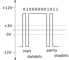
| Value | Name | Voltage |
|---|---|---|
| 0 | Space | +3 to +12 VDC |
| 1 | Mark | -3 to -12 VDC |
Note: -3 to +3 is undefined value.


